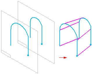
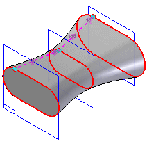
Creates a construction surface by fitting through a series of profiles.


Cross sections can be defined by drawing a profile, selecting existing sketch elements or selecting edges of surfaces.
You can also use a guide curve to define a path between the cross sections of the loft.
The end condition, or Extent, options allow you to control the shape of the loft feature where it meets the first and last cross sections.
The loft feature is associative to the input elements, regardless of the element type you use to define the cross sections and guide curves.
When you create a lofted surface using a closed profile you can use the Open Ends and Close Ends options on the command bar to specify whether the ends of the surface are open or closed. When you set the Close Ends option, planar faces are added to the ends of the feature to create a closed volume.
Note:
You can select wireframe elements from multiple Parasolid bodies or sketches and the elements will remain associative.
Note:
While in Ordered modeling, the Lofted Surface icon may need to be added to the command ribbon. Search Solid Edge help for the phrase “Customize the command ribbon” to learn more about including any missing command, such as lofted surface.
Note:
If you use sketches, you can only select elements from one sketch for each cross section.
You cannot combine elements from a sketch with edges to define a cross section.
When working with loft features that have many cross sections and guide curves, you should consider drawing sketches first, rather than drawing the profiles as you construct the feature. This approach can make it easier to construct and edit the feature.