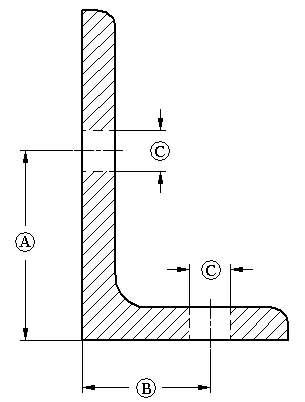
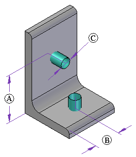
A frame component may contain information on where holes can be drilled.
Hole locations (A, B) are defined in the frame cross section.
Hole diameter (C) represents the maximum allowed hole size.
Hole position along a frame is specified during the assembly hole feature creation. A cylindrical construction surface added to the frame component defines the hole location.


You create holes in frames by adding assembly hole features in the Assembly environment. Use the cylindrical construction surfaces and sketch relationships in each frame member to create hole assembly features in the desired locations. You can use the Include command to include edges from the construction surfaces to aid in aligning the assembly hole features.
If hole location construction surfaces exist in the cross section component file, they do not appear on the frame members by default when the frame is created. You must use the Hole Location→Retrieve from Cross Section Component command on the frame shortcut menu to bring these surfaces into the frame.
You can hide construction surfaces by choosing the Show/Hide Component→Surfaces command on the shortcut menu.
You also can delete the construction surfaces from the frame by choosing the Hole Location→Delete from Frame command on the shortcut menu. Use the Retrieve from Cross Section Component command to restore them if needed.