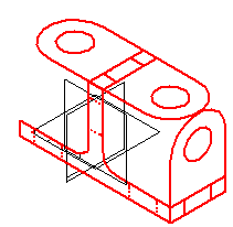
Drawing ordered sketches allows you to establish the basic functional requirements of a part before you construct any features. You can draw a sketch on any reference plane using the Sketch command in the Part and Sheet Metal environments. Then you can use these sketches to create profile-based features.
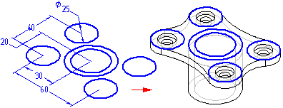
Sketching a part before modeling it gives you several advantages:
Allows you to draw multiple profiles on one reference plane.
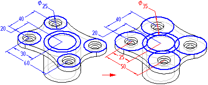
Allows you to define relationships, such as tangency or equality, between profiles on different reference planes.
Allows you to draw the profiles you want without creating the subsequent features until later.
When you click the Sketch button and then select a reference plane or planar face, a profile view is displayed. You can then use the drawing commands to draw 2D geometry.
The sketch elements you draw are assigned to the active layer. For example, when working with a complex sketch that will be used to construct a lofted feature, you may want to arrange the elements on multiple layers.
Note:
For more information about 2D drawing in Solid Edge, see the following related topics: Drawing in Solid Edge and Drawing Profiles.
You can add dimensions and relationships to control the positions and sizes of the profiles. You can also define functional relationships using the Variables command. You can use the Save and Save All commands to save the sketch while you create them. When you have finished drawing, close the profile view using the Return button on the command bar.
For more information on drawing sketches, see the Drawing 2D elements Help topic.
Sketches are represented in the PathFinder tab just like features are. You can display or hide them from the feature tree with the PathFinder Display: Sketches command on the shortcut menu. You can use PathFinder to reorder or rename a sketch just as you would any feature.
You can control the display of all the sketches in a document or individual sketches. To display or hide all sketches, use the Show All: Sketches and Hide All: Sketches commands. To display or hide individual sketches, select a sketch in the application window or PathFinder, then use the Show and Hide commands on the shortcut menu.
You can also control the display of elements in a sketch by assigning the sketch elements to a logical set of layers, and then display or hide the layers to control the display of the sketch elements.
When a sketch is active, it is displayed using the Profile color. When a sketch is not active, it is displayed using the Construction color. You can set the colors you want using the Options command.
You can use sketches to construct features in the following ways:
Directly, by clicking the Select From Sketch button on the feature command bar.
Indirectly, by clicking the Draw button on the feature command bar and then associatively copying sketch geometry onto the active profile plane using the Include command.
You can use sketch profiles directly if no modifications to the profile are required. When constructing an ordered feature, click the Select From Sketch button on the feature command bar. You can then select one or more sketch profiles. When you click the Accept button on the command bar, the profiles you selected are checked to make sure they are valid for the type of feature you are constructing. For example, if you are constructing an ordered base feature, the profile you select must be closed. If you select an open profile or more than one profile, an error message is displayed. You can then select the Deselect (x) button on the command bar to clear the selected profiles.
Ordered features constructed using sketched profiles are associative to the sketch and will update when the sketch is edited.
If the sketch profile requires modification before using it to construct a feature, you must first copy it to the active profile plane using the Include command. When you click the Draw Profile button on the feature command bar, and define the profile plane you want, a profile view is displayed. You can then use the Include command to copy elements from sketch profiles to the active profile plane.
After you have copied sketch elements, you can use the drawing commands to modify them. For example, you may need to add elements to the profile not contained in the sketch. You can also add dimensions and relationships between the elements on the active profile plane and the sketch.
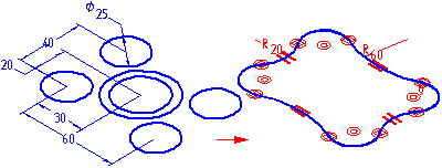
The sketched elements you copy are associative to the sketch and will update if the sketch dimensions are edited.
You can modify sketch elements using the command bar or the element's handles. When you modify an element, other elements may also change.
You can use the Select Tool to select elements in several ways:
To select an individual element, position the cursor over the element and click when the element highlights.
To select multiple elements, press the Ctrl or the Shift key while you select the elements.
To select all 2D elements, press Ctrl+A. The Select Tool command does not need to be active for this to work.
To deselect an element, press the Shift or Ctrl key and click the element.
To select multiple elements using a fence, drag the cursor to define a rectangular fence. You can use the Selection Options button on the Select Tool command bar to specify the selection criteria you want.
After you select an element, you can modify it by changing its values on a command bar. For example, you can change the length of a line by typing a new value in the Length box on the command bar.
You can use an element's handles to modify an element. An element handle is represented by a solid square on the element, such as the end of a line or the center of an arc. You can dynamically drag a handle to modify an element. First, select the element, then drag the handle to modify it.
Lines - Drag a handle to modify the length or angle of a line.
Arcs - Drag an endpoint, midpoint, or center point handle to modify an arc.
Fillets and Chamfers - Drag the handle to modify the size of a fillet or chamfer.
Sketches that are used for constructing revolved ordered features must have an axis defined in the sketch. If you select a sketch profile that does not have an axis, an error message is displayed. You will have to cancel the revolved feature you are constructing, then open the sketch to define the axis.
Drawing sketches can be especially useful when constructing swept and lofted features. Because the Sketch command allows you to define relationships between profiles on separate planes, you can more easily define the relationships you need to control these features properly. Additionally, the ability to exit a sketch profile window without creating a feature can be especially useful when drawing the profiles for swept and lofted features.
You can use the Create 3D command to convert two-dimensional drawing view data into a three-dimensional sketch.
The command displays the Create 3D dialog box that prompts you for the drawing view elements you want to include in the sketch.
Before selecting the elements that you want to include in the sketches, you need to select a template to create a part, assembly, or sheet metal file. After you select a template file, specify the projection angle that you want to use when the sketches are created in the new document. After you specify the projection angle, select the view type of the elements you want to include in the sketch:
Folded principal views are orthogonal or aligned with the primary view. You can select this view type to define the primary view.
Folded auxiliary views are true auxiliary views that are generally derived from principal views and require a fold line to determine the edge or axis around which you want to fold the view.
Copy views are not orthogonal and they may not actually align with the primary view. These views are placed as sketches on the same plane as the last principal view defined in the draft file.
After you define this information, you are ready to select the geometry to create the sketches. You can include lines, arcs, circles, curves, and polylines and line strings created with imported data. You can drag the mouse to fence elements or press the Shift key and click each element to select more than one element.
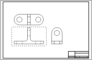
If you select the Fold Principal Views option or Fold Auxiliary Views option and it is not the primary view, you can click the Fold Line button after you select all of the elements for the view. The Fold Line button allows you to define a line or point in an orthogonal or auxiliary view on which to fold the primary view.
If you want to define another view, click the New View button and select the next view.
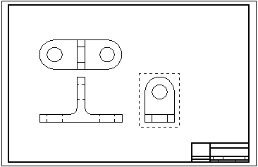
Continue this process to define any additional views.
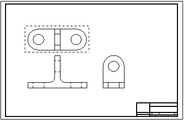
After you define all views, click the Finish button to launch the Part or Sheet Metal environment to create the model file in which the views are placed as sketches.
