 Component Sketch command
 Component Sketch command
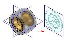
Opens a sketch window so you can create a component sketch, which you can use later when working with virtual components.

You can create multiple component sketches for a single document that represent different view orientations of the component. You use a component sketch as the 2D representation for a part or subassembly when you place an existing component into the virtual assembly structure as a pre-defined component. When you add the existing component to the virtual assembly, you can specify which component sketch you want to use. This allows you to place the same component multiple times at different orientations.
There are two types of graphics you can create in a component sketch: component image graphics, and wireframe graphics. Component image graphics are created using the Component Image command. This command creates a 2D representation of the visible edges on a part.
Component image graphics are not individually selectable in the assembly sketch, but provide a reference envelope.
You supplement the component image graphics with wireframe graphics you create using the Include command or drawing manually. These wireframe graphics can be selected and used for constraining the component sketch in the assembly sketch.
You typically would create both type of graphics for a component sketch. In some cases, you may only create component image graphics, then use the virtual component symbol origin to constrain the pre-defined component in the assembly sketch.
The sketches you create are added to Feature PathFinder or Assembly PathFinder in a section reserved for virtual component sketches.
For more information on working with virtual components, see the Creating and Publishing Virtual Components Help topic.