 Explode command
 Explode command
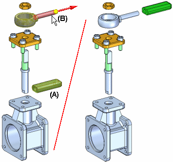
Explodes one or more parts in a specified direction. The parts (A) selected for explosion are offset along an explode vector you define by selecting a face or reference plane on a base or reference part (B).

You can manually explode a single part, multiple parts, and bound subassemblies. You define the offset distance using the Distance box on the command bar.
Note:
Parts that were exploded with the Automatic Explode command can be re-exploded along a different explode vector using this command.
The basic steps for manually exploding parts are:
Select the parts to explode.
Select the base part.
Select a face or reference plane on the base part.
Specify the explode direction.
When you select multiple parts to explode in one operation, you can use the Manual Explode Options dialog box to specify whether the parts are spread out evenly, or that the parts are moved as a single unit.
When you set the Spread Components Evenly option, you can use the Manual Explode Options dialog box to define the explode order you want. You can select one or more parts in the Explode Order list, then use the Move Up and Move Down buttons on the dialog box to define the explode order you want. When you select a part in the list, it highlights in the graphic window. This allows you to reorder the parts as you explode them.
When you set the Move Components as a Single Unit option, the current relative position of the set of parts is maintained, and they are relocated along the explode vector you defined.
When you select a bound subassembly to explode, it is exploded as a single unit. In other words, the components within the subassembly are not spread out.