Choose Home tab→Drawing Views group→Auxiliary View  .
.
A representation of the viewing plane line is attached to the cursor. The auxiliary view will be rotated 90 degrees about the viewing plane line.
Move the cursor around on the drawing sheet. When the cursor locates a linear element, the viewing plane line attached to the cursor becomes parallel to the element.
Do one of the following:
Click a located line to define it as the viewing plane line.
Draw a viewing plane line by clicking two key points in the part view. The new line is automatically defined as the viewing plane line.
The cursor becomes a rectangle that represents the size of the view that you are going to create.
Position the auxiliary view where you want it, then click.
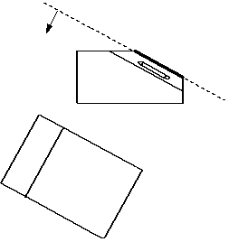
Where you place the view determines the direction of rotation of the auxiliary view. The viewing plane is rotated toward the view location, as shown in the figure.


Tip:
You can create auxiliary views from both principal views and existing auxiliary views.
You can define the viewing plane line by selecting a linear edge or by clicking two key points in a principal part view.
The viewing plane line and auxiliary view are associative to the principal view. If the geometry in the principal view changes, the viewing plane line and auxiliary view update.
You can move the viewing plane line in any direction using Shift+drag.
You can use the Drawing View Style list on the Auxiliary View command bar to choose a display style for the auxiliary view line. You also can modify the appearance of an existing viewing plane line using the View Plane Properties dialog box.