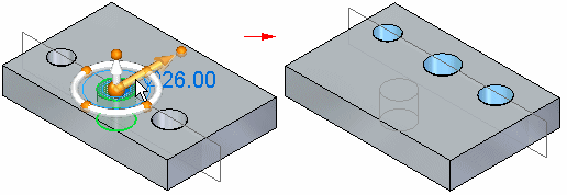
The Live Rules panel appears in the document window when you start any of the following types of synchronous modeling operations:
Move or rotate model faces, features, and so forth in a synchronous part or assembly document.
Define a 3D geometric relationship between model faces in a synchronous part document.
Edit the value of a 3D dimension in a synchronous part or assembly document.
By default, Live Rules appears in a fixed location at the bottom center of the document view. Live Rules can also appear as a floating horizontal or vertical floating panel. These settings are in the Solid Edge options Helpers page.
The Live Rules panel contains the relationship types to detect during a synchronous modeling modification.
Note:
When pausing the cursor over any option on the Live Rules panel, the character shown in parenthesis (1) indicates the shortcut key you can use to turn the option on or off.

Suspends all Live Rules during a synchronous edit.
Relaxes locked dimensions during a synchronous edit.
Relaxes persisted relationships during a synchronous edit.
Restores the default rule Live Rules settings.
Creates persistent relationships for all found live rules.
Considers reference planes when applying Live Rules.
Considers sketch planes when applying Live Rules.
Considers coordinates systems planes and axes when applying Live Rules.
 Concentric (C)
Specifies that you want to maintain concentricity between the select set and the rest of the model.
 Tangent Edges (T)
Specifies that you want to maintain edge tangency between the select set and the rest of the model.
 Parallel (L)
Specifies that you want to maintain parallelism between the select set and the rest of the model.
 Coplanar (P)
Specifies that you want to maintain coplanarity between the select set and the rest of the model.
 Tangent Touching (G)
Specifies that you want to maintain touching tangency between the select set and the rest of the model.
 Perpendicular (D)
Specifies that you want to maintain perpendicularity between the select set and the rest of the model.
Specifies that you want to maintain symmetry between the select set and the rest of the model along the specified plane.
Specifies that you want to maintain symmetry about the base XY plane.
Specifies that you want to maintain symmetry about the base YZ plane.
Specifies that you want to maintain symmetry about the base ZX plane.
Specifies that you want to maintain symmetry about a custom symmetry plane. When you click this button, you can select a reference plane or coordinate system plane about which you want to maintain symmetry for the modification.
Planar faces that are coplanar to a base reference plane are locked to the that base plane. Cylindrical faces that are coaxial to a base global system axis are locked to that global axis. This setting is ON by default.
Note:
Sheet metal bends do not honor the Lock to Base Reference (B) option.
Specifies that you want to maintain the coplanar axial alignment between the select set and the rest of the model along the specified axis.
This option is useful for maintaining the alignment of cylindrical faces whose axes are aligned along a common theoretical plane.

This option is available only for faces or features that have an axis, such as cylinders, cones, holes, and manufactured features that have a feature origin, such as dimples in a sheet metal model.
Specifies that you want to maintain axial alignment for cylinders lying in the XY plane.
Specifies that you want to maintain axial alignment for cylinders lying in the YZ plane.
Specifies that you want to maintain axial alignment for cylinders lying in the ZX plane.
Maintains all canted coplanar axes found in the model.
Specifies that you want to maintain the current radius values as much as possible when the model is modified.
When cleared, radius values can change as required to complete the operation.
Specifies that you want planar faces to stay orthogonal to the base reference planes as much as possible when the model is modified.
When cleared, planar faces may tilt as much as required to complete the operation.
Specifies that all the faces in the sheet metal model with the same thickness chain as the select set are modified as a group when the model is modified.
![]()
When this option is cleared, only the faces in the select set and faces in other thickness chains that satisfy active relationships are modified.
![]()