You can create new documents in the following ways:
On the Solid Edge startup screen, under Create, you can click a link to open a new document using the default template for that environment.
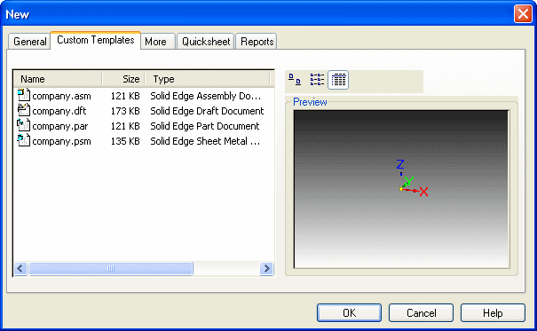
On the Application menu, you can choose the New command and then select the environment-specific template you want from the New dialog box.
English and metric templates are delivered with Solid Edge for each environment:
Assembly
Draft
Part
Sheet Metal
Weldment
Solid Edge provides templates supporting standards, such as ISO, DIN, JIS, ESKD, and GB.
When you create a new document, it is given a temporary file name and extension that corresponds to the environment you are in. For example, if you create a new part document using the default template, the document is given a temporary name with a .par file name extension.
Any changes you make to the document are temporarily stored in memory. You have to save the document to preserve the changes to your document. The first time you save the document, you can define a permanent document name and folder location using the Save As dialog box.
Regardless of the method you use to create a document, a document template is used as a starting point. A template is a document that provides default settings for text, formats, geometry, dimensions, units of measurement, and styles that are used to produce a new document.
You can edit the property set of the standard templates to include default values for some of the properties as well as the additional custom properties you need to manage your documents. For example, to make it easier to create drawings that conform to your company's standards, you should consider defining a custom Draft document template where the dimensioning and annotation standards for your company have been defined.
Property text is text that is associative to properties in the current file, as well as to properties in models attached to the current file. You can use property text strings to retrieve file or model-related data and display it in your drawing border template or title block. Using property text ensures that the information remains updated without manual editing.
All standard Solid Edge file properties, such as title and file name, are available for use as property text. Properties that can be computed from data in the file, such as active sheet and number of sheets, are also available. Properties such as Company, Project, Revision Number, Document Status, and Last Printed Date can be extracted directly into the title block of a drawing border template.
To learn more about property text in blocks, see the Help topic, Using Blocks. To learn how to create and edit property text in general, see Using Property Text.
When you create custom templates for your company, you can put them in the Solid Edge ST5\Template folder or you can create your own company-specific template folder. If you create a company-specific template folder, the folder should be a subfolder in the Solid Edge ST6\Template folder. For example, if your company's template folder is named Custom Templates, the path to the folder would be Solid Edge ST6\Template\Custom Templates. When you create a subfolder within the Solid Edge ST6\Template folder, a tab is added to the New dialog box with the same name as the subfolder. This makes it easier for your company to access your custom templates.

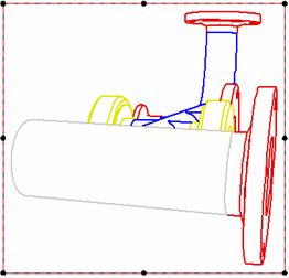
In the Draft environment, you can apply model colors assigned using Color Manager and Part Painter to edges shown in drawing views.

The following options are available to apply model colors to drawing views:
Select the Use model colors option on the Shading and Color page (Drawing View Properties dialog box). You can select Use model colors, and then choose to apply the part base color style, the assembly override color style, or both to drawing view edges.
Use the Edge Painter command to:
Show purchased parts in one color and manufactured parts in another color.
Assign a unique color to all newly designed parts on a drawing.
Apply assembly weld colors to weld bead graphics.
The Solid Edge Draft environment provides a color scheme specifically designed to emulate the AutoCAD environment. The AutoCAD Model color scheme sets the sheet color to black, and it sets default highlight, element selected, element disabled, and handle colors. You can drag AutoCAD .dxf and .dwg files onto the Solid Edge sheet, and they will display using the AutoCAD color scheme and template colors.
Color scheme is set per sheet type: working sheet, 2D Model sheet, and background sheet. For consistent graphics display, you should select the same color scheme for each sheet. To select and apply the AutoCAD color scheme, first display the working sheet or the 2D Model sheet, and then select AutoCAD Model from the Color Scheme list on the Colors page of the Solid Edge Options dialog box.
Note:
Changing the color scheme may cause all your graphics to disappear. If this happens, change the color scheme setting back to Solid Edge Default. Then you can experiment with individual color overrides using the Properties command on the shortcut menu of a selected element, or make global changes using the Styles command on the View tab.
There also are Solid Edge drawing border block files that support the AutoCAD color scheme. These block files contain drawing borders in different sizes, as well as default title blocks. You can select and place these AutoCAD-friendly drawing borders on the 2D Model sheet when you select the Drawing Area Setup command.
For Solid Edge 3D models, the Quicksheet template is a special kind of template that you can use to quickly generate 3D views. The Quicksheet template is a drawing template that contains drawing views that are not linked to a model. When you open a document using a Quicksheet template, it looks something like the following:

You can drag a model from the Library docking window or from Windows Explorer onto the template, and the views populate with the model.
To create a Quicksheet template, configure drawing views of the type and with the properties you want, then select the Create Quicksheet Template command. A message box is displayed advising you to save your current work before the drawing views are emptied. When you click Yes, you can save the file with the name and location you want, and the Quicksheet template is ready for use. When you create a Quicksheet template, all drawing views on all sheets are emptied, including parts lists. Almost all view properties, including general properties, text and color properties, and annotation properties, are maintained.
To learn more about creating drawing views, see the Help topic, Drawing View Creation.
Import Solid Edge Templates into Insight XT