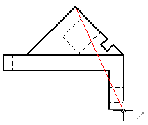
The Auxiliary View command creates a new part view that shows the part rotated 90 degrees about a folding line. The drawing view is created from the axis of this fold line. You can create auxiliary views from principal views and existing auxiliary views.
The cursor is displayed as a line that is used to define the folding line. The auxiliary view is created perpendicular to this folding line. To define the folding line, move the cursor across the drawing view to highlight an edge that is perpendicular to the desired auxiliary view.

You also can define the folding line for a new auxiliary view by selecting two keypoints using existing drawing view edges. Two points are required when a single, linear element does not exist along the angle of the desired auxiliary view.

After defining the folding line, the cursor is displayed as a rectangle that is roughly the size of the auxiliary view. To place the view, move the rectangle on the sheet to position the view, and then click.

After you place the auxiliary view, you can:
Move the viewing plane line in any direction using Shift+drag.
Change the viewing plane line type, caption, and style in the Viewing Plane Properties dialog box.
You can control caption display and formatting separately for the auxiliary view and for the viewing plane line used to create it. In addition to showing and hiding caption text using the Show Caption button on the command bar, you can change the content and formatting of a caption.
When you select a viewing plane line, you can use the Caption tab (Viewing Plane, Detail Envelope, Cutting Plane Properties dialog box).
When you select an auxiliary view, you can use the Caption tab (Drawing View Properties dialog box).
You can reposition a caption by selecting the view and then dragging the label to a new location.
The default viewing plane caption content and formatting is defined in the Drawing View style that is applied to the auxiliary view. To learn more, see the following Help topics: