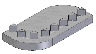
Use the Pattern Along Curve command  to construct a pattern of selected elements along a specified curve. You can select features, faces, face sets, surfaces, or design bodies as the parent elements to pattern. You can control how the pattern follows the curve by customizing parameters such as start point and transformation type, as well as occurrence count, spacing, and orientation.
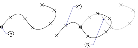
You can pattern the elements along any 2D or 3D curve or model edges. For example, you can pattern a feature (A) along a set of sketch elements (B).

Note:
Pattern features are associative to the parent elements. If you modify the parent elements, the pattern updates. If you delete the parent elements, the pattern is deleted.
The first step in constructing a pattern along a curve is selecting the elements to pattern. You can select the elements to pattern in PathFinder or the graphics window.
After you select the elements to pattern, you can select any 2D or 3D sketch, curve, or model edges to pattern the elements along.
After you select the pattern curve, you can configure the pattern. First select the pattern anchor point. The anchor point is the point where the pattern begins. The anchor point must be a keypoint on the pattern curve. Use the dynamic arrow on the anchor point to select the direction in which the pattern goes.
After you define the anchor point and direction, you can use the options on command bar to define the number and spacing of occurrences with the Pattern Type, Count, and Spacing options. When the Pattern Type is set to Fit, the pattern operation places the number of occurrences specified by the Count option, equally spaced. When the Pattern Type is set to Fill, the pattern operation places as many occurrences as fits on the curve, with the distance specified by the Spacing option between each occurrence. When set to Fixed, the pattern operation places occurrences using both the Count and Spacing options.
You can customize the transformation and rotation of the pattern to better capture your design intent. You can specify that occurrences be placed in the pattern linearly, keeping the same orientations throughout the pattern. Or, you can specify a transformation that will change the orientations of the occurrences depending on the input curve or a specified plane.
The reference point is the point in the pattern at which transformation begins. By default, the reference point is the anchor point (A). To select a different reference point, click the Reference Point button on the command bar and click a new point on the pattern (B). The pattern transforms to the new position (C).

A linear transformation orients occurrences based on the orientation of the patterned elements.

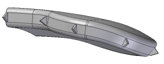
A full transformation orients occurrences based on the input curves.

A transformation from plane projects the initial occurrence and a target occurrence onto a plane, where a measured angle defines occurrence orientation.

You can also use the Rotation Type control to specify whether the input feature position or input curve position determines occurrence placement.
You can suppress occurrences in patterns along curves with the Suppress Occurrence button on command bar. After you click the Suppress Occurrence button, click the occurrence symbols for the occurrences you want to suppress. You can suppress individual occurrences, or you can use a fence to suppress adjacent multiple occurrences.
You can insert occurrences in patterns along curves with the Insert Occurrence button. After you click the Insert Occurrence button, you can click a keypoint to insert an occurrence. Use the Offset option to control its offset.
You can add new elements to an existing pattern using the Add to Pattern button on the command bar when you are editing an existing pattern. For example, if you add a chamfer feature to the original feature that was patterned, you can edit the pattern feature, then use the Add to Pattern button on command bar to select the chamfer and add it to the pattern.
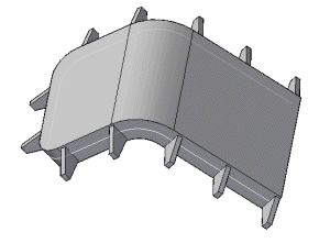
You can pattern multiple elements in one operation.
You can suppress individual pattern occurrences in a pattern along a curve.
You can insert individual feature occurrences into a pattern along a curve.