 Thread command
 Thread command
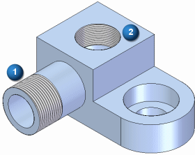
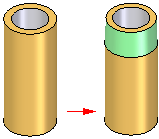
Adds a straight or a tapered thread reference to an existing cylindrical face. The cylindrical face can be a partial or complete cylinder, and can be an external (1) or internal (2) face. A planar, circular edge is required to define the start end for the threads.

Threads can be added either internally or externally. When constructing tapered threads, you do not need to construct a conical face. You add a tapered, threaded feature to a cylindrical face, and when you finish the feature, the taper angle is added to the threaded portion of the cylinder.

Threads can be added to both ends of a cylinder.

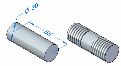
For internal threaded holes, you should use the Hole command whenever possible. For external threaded features, such as threaded rods, shafts, and external pipe threads, you should use the Thread command.
Because you use the Thread command to add thread information to an existing cylindrical face, the cylindrical face diameter must match a value listed in the Holes.txt or PipeThreads.txt files.
For external threads, the cylinder diameter (1) must match a value in the nominal diameter column in the Holes.txt or the PipeThreads.txt files. For internal threads, the cylinder diameter (2) must match a value in the internal minor diameter column in the Holes.txt or the PipeThreads.txt files.

For example, to add a Rd 24 x 1/8 metric straight pipe thread to an external cylinder, the cylinder diameter must be exactly 24 millimeters, which matches the nominal diameter for this thread in the PipeThreads.txt file.
To add the Rd 24 x 1/8 metric straight pipe thread to an internal cylinder, the cylinder diameter must be exactly 21.142 millimeters, which is the internal minor diameter for this thread in the PipeThreads.txt file.
Note:
In ordered, if the cylindrical face diameter does not match a value in the Holes.txt or the PipeThreads.txt files, the Thread Type list on the Thread command bar will be blank and a warning message is displayed when you click the Finish button.
Note:
In synchronous, if the cylindrical face diameter does not match a value in the Holes.txt or the PipeThreads.txt files, the closest thread size in the list is selected.
The Holes.txt and PipeThreads.txt files are ASCII text files that are used to populate thread size values on the Thread Type box on the Thread command bar. You can use a text editor, such as Notepad, to add or edit values in these files. You can also print these files to make it easier to define the correct matching cylinder diameter for the thread size you want to use.
By default, the files are located in the C:\Program Files\Solid Edge ST6\Preferences folder. You can instruct Solid Edge to look for these files in a different folder, including a folder on another machine on the network. On the File Locations tab on the Options dialog box, select the Hole Size File or Pipe Threads File entry, then click Modify. On the Browse dialog box, specify the drive and folder containing these files. After specifying the location, click Update.
Note:
If you edit the Holes.txt or PipeThreads.txt files, save a copy of these files before you uninstall Solid Edge.
When working in an assembly, you can use this command to construct an assembly feature.