When constructing one or more holes in the synchronous environment, you dynamically drag the hole onto any face in the model.
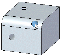
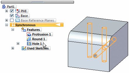
Holes may be placed on multiple reference objects within the same instance of the command. All holes created within one instance of the command will share the same attributes.
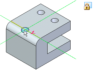
When placing a hole feature, you lock to a plane by pressing the F3 key, clicking the lock icon ![]() while pausing the cursor over a plane, or when you place two hole occurrences on the same face within the same instance of the command, the plane automatically locks.
while pausing the cursor over a plane, or when you place two hole occurrences on the same face within the same instance of the command, the plane automatically locks.
Plane locking is helpful when placing multiple holes on a single face because all holes are placed with respect to the same plane regardless of where you drag the cursor. Once you lock to a plane, you can use edge references to more precisely define the hole location with dimensions.
When you lock to plane, the locked plane icon is displayed in the upper right corner of the graphics window and planar alignment lines are displayed on the locked plane.
When locked to a plane in the hole placement workflow, dimensions may be placed on each occurrence dynamically.
Press E to create dimensions from the center of the circle to the closest edge endpoint.
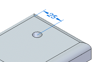
Press C to create dimensions from the center of an existing circle.
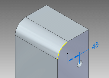
Before the hole is placed, you can type a dimension value and the dynamic movement is locked to the defined value. You can redefine the dimension from the keypoint in a different direction, by either pressing the Toggle Dimension Axis button ![]() on the command bar, or pressing T.
on the command bar, or pressing T.

All precise placement dimensions are maintained as PMI dimensions after the hole is placed.
You can use the M option to align a hole to the midpoint of a highlighted edge. Upon hole placement, a horizontal/vertical relationship is created.
When you pause the cursor over an existing hole, the hole center point highlights. Pressing the A key begins the hole alignment. As you move the hole, alignment lines display on the face when the hole position is horizontal or vertical with the existing hole axis. You can align the hole on other faces in the model. As you move the hole on other faces, the alignment lines also display. You may need to press the N key to highlight the edge on the face that is parallel to the alignment lines. You can position the hole on a circular face also. The alignment lines display on the circular face as you move the hole over the circular face.
When placing a hole on a cylinder, press F3 as the cursor moves over the cylinder. The Tangent plane command activates. You can position tangent plane by dynamically dragging or by entering an angular value and then press Enter. Once the tangent plane locks, you can drag the hole over the tangent line (C) and the hole locks to the tangent line.
![]()
While in the Hole command you can place dimensions between the holes. You can also dimension the holes after the holes are placed.
![]()
Use the Type option on the Hole Options dialog box defines the type of hole you want. You can construct several types of holes:
(A) simple holes
(B) threaded holes
(C) tapered holes
(D) counterbore holes
(E) countersink holes
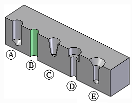
You can only define one type of hole for a single hole feature. To construct a different type of hole, you must construct another hole feature.
The options available on the Hole Options dialog box change, depending on the type of hole you specify. For example, when you set the Threaded option, new options are displayed so you can specify the thread type you want.
You can specify a straight thread, a standard pipe thread, or a tapered pipe thread when you set the Type option to Threaded. You can also specify standard or straight pipe threads when you set the Type option to Counterbore or Countersink.
For threaded holes, the size of the hole in the solid model matches the minor thread diameter listed in the Holes.txt file or PipeThreads.txt file for the thread size you selected. For example, when you construct a M24 x 1 metric threaded hole, the hole diameter in the solid model will be 22.917 millimeters, as this is the minor thread diameter listed for this thread in the Holes.txt file.
A different face style is used to indicate that a hole is threaded. The Color Manager command provides an option to define the Face style for Threaded Cylinders. The default value for the Threaded Cylinder option is the Thread style. With the Thread style, you can also use the Rendering tab on the Format View dialog box to specify whether a photo-realistic texture is applied to threaded features in a shaded view.
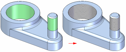
For more information, see the Threaded Features Help topic.
You can use several extent types when constructing holes:
Through All
Through Next
Finite Extent
The extents that are available depend on the type of hole you are creating. Simple holes, counter bore holes, countersink holes, and threaded holes support all three extent types. Tapered holes support only the Finite Extent option, but you can define a finite extent length that exceeds the thickness of the part.
With counter bore holes, if you use the Finite Extent option, you define only the hole extent. The counter bore extent is defined by the Counter bore Depth value you specify on the Hole Options dialog box.
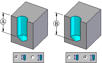
When you construct a hole using the Finite Extent option, you can use the V Bottom Angle option to specify whether the bottom of the hole is flat or V shaped.
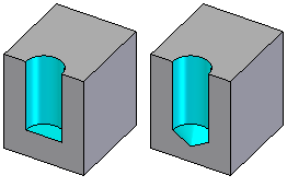
When you set the V Bottom Angle option, you can also type a value for the bottom angle. The angle you specify represents the total included angle. You can also specify how the finite depth value is measured.
You can specify that the depth dimension is applied to the flat portion of the hole where the V bottom angle begins (A), or that the hole depth dimension is applied to the V bottom of the hole (B).
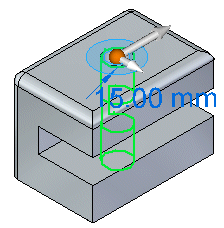
When you place a hole, an Edit Definition handle is created so that you can change dimension values for existing holes. To change the dimension value, click the hole dimension,
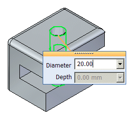
type a new value, and press Enter.
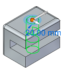
The dimension changes to reflect the new value.
You can click the Options button on the command bar to display the Holes Options dialog box if you want to change the hole type.
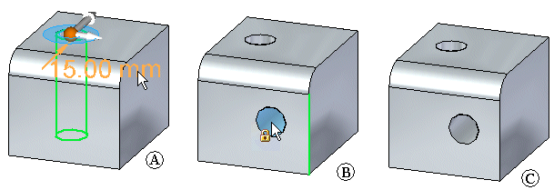
After placing a hole, you can add additional occurrences of the hole. To add more hole occurrences, click the dimension for the hole (A), click the More Holes button  , drag the cursor to the new location (B), and click to place the new occurrence of the hole (C).
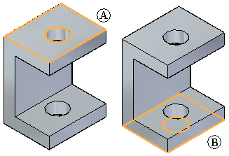
Creating a through all hole on a c-shaped model creates a from-to extent from the top plane (A) to the bottom plane (B).
Suppose you create a protrusion below the face,
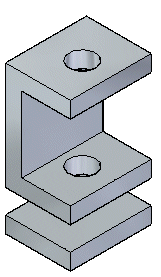
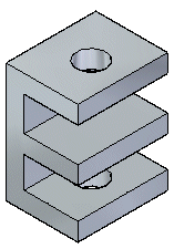
or a protrusion between the two faces.
If you edit the dimension of the hole,
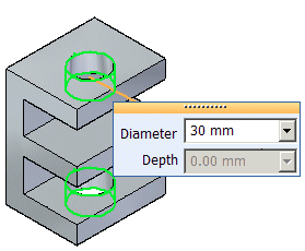
the hole dimension is updated, but the hole does not pass through the new faces.
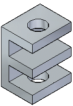
Also, if you change the hole type, the change is applied only to the existing faces. The new faces remain unchanged.
In the following example, two 100 mm finite depth holes are placed as a group in a block.
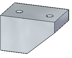
The hole on the left does not penetrate the entire depth of the block and is capped.
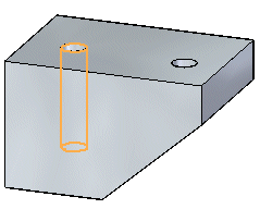
If you select the handle of the hole on the left, you can change the depth and diameter for the hole.
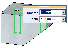
Also notice that the hole type on the command bar is set to Finite Depth.

The hole on the right penetrates the entire depth of the block and is not capped. Because it is not capped the hole extent for the hole is changed from finite depth to through next.
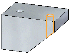
If you select the handle of the hole on the right, you can change the diameter of the hole, but not the depth of the hole.
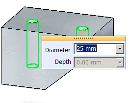
Also notice that the hole type on the command bar is set to Through Next.

Suppose you select the highlighted face (A) and drag it to a new position (B).
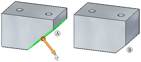
If you select the hole on the right for edit it remains a from-to hole and is not capped.
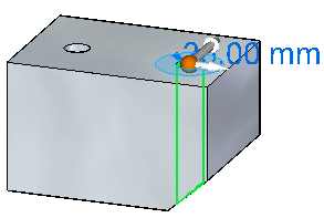
If you change the diameter for the hole, the diameter changes, but the hole type remains from-to.
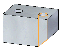
If you change the hole type to Finite, the hole depth changes to the original depth of 100 mm.
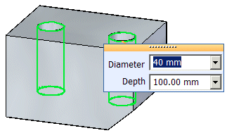
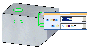
If you change the depth of the hole, the depth for both holes in the group changes.
The Holes.txt and PipeThreads.txt files are ASCII text files that are used to populate hole size values on the Hole Options dialog box. You can use a text editor, such as Notepad, to add or edit values in these files. By default, the files are located in the C:\Program Files\Solid Edge ST6\Preferences folder.
You can use Hole Size File or Pipe Threads File entry on the File Locations tab of the Options dialog box to instruct Solid Edge to look for these files in a different folder, including a folder on another machine on the network.
Use the Saved Settings options on the Hole Options dialog box to save commonly used hole parameters to an external file, named CUSTOM.XML. You can then use the Saved Settings list on the Hole Options dialog box or the Hole command bar to select a saved setting later in any Solid Edge document where you can construct hole features.
Similar to the Holes.txt file, you can use the File Locations tab on the Options dialog box to specify a folder for the Custom.xml file.
When you specify a machine on the network for the Holes.txt, PipeThreads.txt, and Custom.xml files, all users can use the same parameters for the hole features they construct, which makes it easier to enforce company and industry standards.