The Simulation Results environment now provides an improved results display for a model that contains a mix of solids and surfaces or united bodies. These enhancements are displayed for part, sheet metal, and assembly models.
All of the result plots now are displayed on the model at the same time. Previously, you could display the surface results or the solid results, but not both at once.
Example:
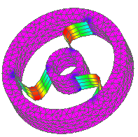
This part, which contains surfaces united with solids using the Unite Bodies command, was meshed with the General Bodies mesh type.

Plate thickness is applied to surfaces using two new options:
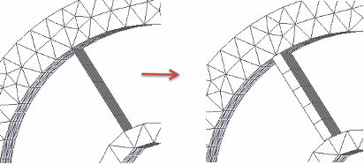
In the Mesh dialog box, you can select the Show surface results option to thicken a surface before meshing the model. This is available for 2D Surface meshes and for Mixed Meshes.

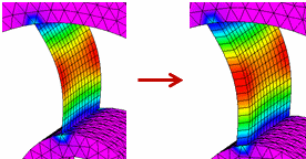
In the Simulation Results environment, you can select the Plate Thickness option on the Home tab→Show group→Display Options menu to apply a thickness to the model surface. This makes it easier to visualize results.

The Plate Thickness display option also affects node values shown by the Minimum and Maximum markers and the Probe command. When the Plate Thickness check box is deselected, these annotations indicate whether a node value is located on the top (Top) or the bottom (Bot) of a surface.
To learn more, see Displaying node data for plates in the Probing analysis results help topic.