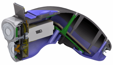
The Solid Edge Assembly environment allows you to easily build, modify, display, revise, and analyze assemblies.

You can build an assembly using existing parts and subassemblies, or you can model new parts within the context of the assembly. You can even use parts that were not modeled with Solid Edge. You can also create layouts in the Assembly environment.
Note:
To place parts that were constructed in other CAD formats, you must first convert them to Solid Edge part files.
When you edit Solid Edge parts and subassemblies, the changes are reflected in the assemblies in which they are placed. For example, if you increase the flange thickness of a part, the other parts in the assembly adjust their positions accordingly. You can also replace a part in an assembly with a different part.
It is sometimes easier to work in an assembly if you hide parts and subassemblies you are not actively working on. Solid Edge makes it easy to display and hide parts. You can also save favorite display configurations for later use.
Solid Edge allows you to view assemblies with different colors applied to different parts. This can make an assembly easier to understand and more interesting when used in presentations.
During the life cycle of a project, you may want to archive parts and subassemblies for your records. The data management tools in Solid Edge help you manage release statuses of parts, subassemblies, and the entire project. When you need to make formal revisions, you can copy, rename, or move selective components or entire projects.
You can perform interference analysis calculations between parts and sets of parts in a Solid Edge assembly. You also can determine the physical properties of parts and assemblies; such as mass, center of gravity, and so forth.
When placing a part in an assembly, Solid Edge determines the position of the part relative to other parts in the assembly.
In the case of directed parts, Solid Edge determines the part position sequentially. In other words, each part is positioned relative to its related parts before proceeding to the next part. The position of a directed part is not affected by a shared relationship with a part that is placed in the assembly after it. You cannot edit a directed part and establish a relationship to a part that is placed in the assembly after it.
In the case of non-directed parts, Solid Edge tries to determine the part position sequentially. If it cannot determine the position sequentially, it will determine it simultaneously.
The following are types of parts that are considered to be directed parts:
All tube parts
All parts that are constrained to another directed part
Once a part is set to directed or non-directed, the state of the part cannot change.
When editing assembly relationships, there are two parts involved. One is the part you are positioning or editing and the other part is the part to which you are constraining.
For non-directed parts, you can constrain to non-directed parts only. For directed parts, you can constrain to either a non-directed part or a non-directed part that comes before the part on which you are placing the constraint.