On the Application menu, click Solid Edge Options.
Choose a Weld Symbol standard on the Drawing Standards tab in the Solid Edge Options dialog box.
Select the Weld Symbol command  in the Annotation group on the Home tab, the Sketching tab, or the PMI tab.
The Weld Symbol Properties dialog box is displayed.
On the General tab (Weld Symbol Properties dialog box), set the properties you want for the weld symbol, and then click OK.
Example:
This in the user interface that is displayed when the ANSI/ISO/DIN Weld Symbol standard is selected.

See the help topic, Example: Define a weld symbol.
Tip:
Even though there are no labels, tooltips are available for every button and box in the dialog box.
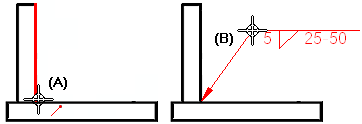
If applicable, click the element you want to use for the terminator end of the weld symbol (A).
Click where you want to place the weld symbol (B).

Tip:
To retrieve weld symbol labels you added to a 3D model, use the Tie to Geometry option on the Weld Symbol command bar.
You can attach a weld symbol to another weld symbol to create a compound weld symbol.
You can double-click a weld symbol to edit its properties.